Kategoriler
Tractor Testing RAAGEN IPX1 IPX2 IPX3 IPX4 WATER SPRAY TEST CHAMBER Automotive RAAGEN RAIN TEST CHAMBER MIL-STD-810 Building Materials Test Cement, Concrete, Bricks, Asphalt and Rock Test Ceramics Glass Test Components Test Composites Test Container & Package Testing Clımatıcs & Envıronmental Sımulatıon MIL STD 810 Testing Structural Dynamıcs Testıng
Measuring Device for Testing Vehicles Equipped with Hydraulic Brakes for the Activation Time of the Brake Actuator According to the Methods of Commission Delegated Regulation (EU) 2015/68 and UNECE Regulation 13
Model: H-BAT-01
The towed vehicle simulator will have the following components and characteristics:
1. Supplementary line towed vehicle simulator
1.1. Supplementary line with a female coupling corresponding to ISO 16028:2006 having an orifice with a diameter of 0,6+ 0,2 mm in order to limit its flow during the test.
1.1.2. Piston accumulator (or equivalent device) complying with the following characteristics and test conditions:
1.1.2.1. Initial precharge pressure of 1 000± 100 kPa at a displaced volume of 0 cm3;
1.1.2.2. Maximum pressure of 1500 kPa at a displaced volume of 500±5 cm3.
1.1.3. The piston accumulator (or equivalent device) is connected with the supplementary line via a connection with an internal diameter of 12,5 mm consisting of a flexible pipe (according to EN853:2007) of 1,0 m length.
1.1.4. A testing port will be provided as close as possible to the female ISO 16028:2006 coupling.
1.1.5. In order to be able to bleed the simulator before and after the test a bleeding device will be provided.
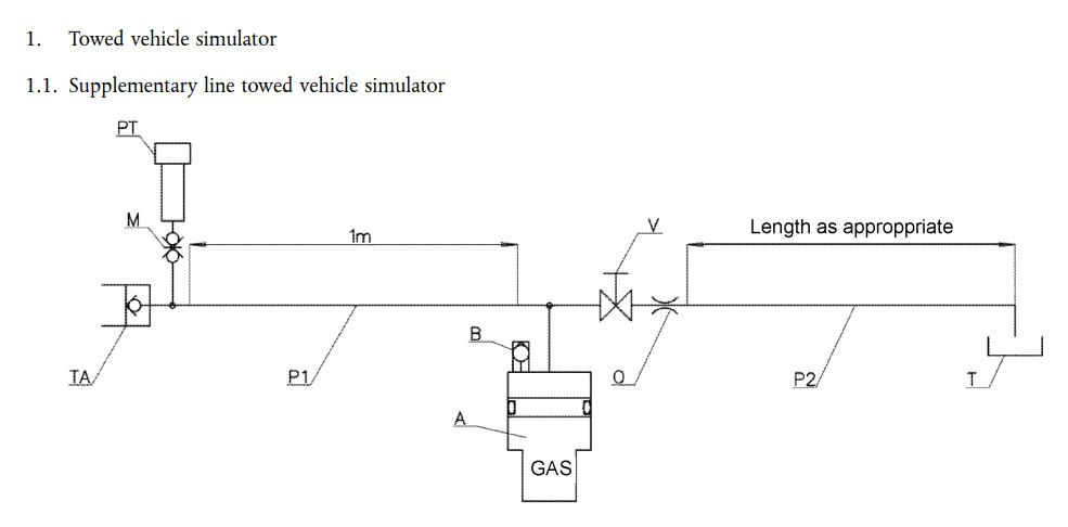
TA = coupling head, supplementary line (female coupling ISO 16028:2006)
M = pressure test port
PT = pressure transducer
P1 = flexible pipe acc. to EN853:2007 with internal diameter 12,5 mm
A = hydraulic accumulator (volume: 1 000 cm3, pre-charge pressure: 1 000 kPa)
B = bleeding screw
V = bleeding device
O = orifice
P2 = flexible pipe with internal diameter 10 mm
T = return to tractor tank
2.Control line towed vehicle simulator
2.1. Control line with a female coupling corresponding to ISO 5676:1983
2.2. Energy storage device with piston (or equivalent device) complying with the following characteristics and test conditions:
2.2.2.1. Initial precharge pressure of 500± 100 kPa at a displaced volume of 0 cm3
2.2.2.2. Intermediate test pressure of 2 200± 200 kPa at a displaced volume of 100±3 cm3
2.2.2.3. Final pressure of 11 500± 200 kPa at a displaced volume of 140±5 cm3
2.3. The energy storage device with piston (or equivalent device) is connected with the control line via a connection with an internal diameter of 10 mm consisting of a flexible pipe (according to EN853:2007) of 3,0 m and a rigid pipe of 4,5 m length.
2.4. Testing ports will be provided as close as possible to the energy storage device with piston (or equivalent device) and to the female ISO 5676:1983 coupling.
2.5. In order to be able to bleed air from the connection pipes before the test a bleeding device will be provided.
2.6. The test will be performed under the following conditions:
2.6.1. The connection pipes will be bleeded from air before the test;
2.6.2. The engine speed of the tractor will be at 25 % above idling speed;
2.6.3. The bleeding device of the supplementary line towed vehicle simulator will be fully opened.
2.7. With regard to the measuring of the response time according to points 3.3 and 3.4, the brake control force will be such to obtain at least a pressure of 11500 kPa on the coupling head of the control line with the engine running at 25% above idling speed. 5. For an actuating time of 0,2 seconds, the time elapsing from the initiation of the braking system control device to the moment when the pressure measured at the testing port close to energy storage device with piston (or equivalent device) reaches 75 % of its maximum value according to point 3.5 will not exceed 0,6 seconds. However, the maximum value relates here to the pressure measured at the testing port instead of the brake pressure as in the case of point 3.5.
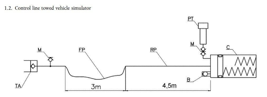
TA = coupling head, control line (female coupling ISO 5676:1983)
M = port for pressure gauge or pressure transducer
FP = flexible pipe acc. to EN853:2007 with internal diameter 10 mm
23.1.2015 EN Official Journal of the European Union L 17/57
RP = rigid pipe with internal diameter 10 mm
PT = pressure transducer
B = bleeding screw
C = cylinder/s (*)
3. The tractor simulator will have the following characteristics:
3.1. The tractor simulator will be fitted with the types of connections as specified in points 2.1.5.1.1 to
2.1.5.1.3 of Annex I with regard to the tractor.
3.2. When the tractor simulator is activated (e. g. by an electrical switch):
3.2.1. A pressure of 11500 + 500 kPa will be generated on the coupling head of the control line,
3.2.2. A pressure of 1 500 + 300 kPa will be present on the coupling head of the supplementary line.
3.3. When the control line of the towed vehicle is not connected, the tractor simulator will be capable of generating a pressure of 11 500 kPa at the coupling head of the control line within 0,2 seconds after it was activated (e.g. by an electrical switch).
3.4. The hydraulic fluid used in the tractor simulator will have a viscosity of 60± 3 mm2 /s at a temperature of 40± 3 °C (e.g. hydraulic fluid according to SAE 10W30). During the tractor simulator test the temperature of the hydraulic fluid will not exceed 45 °C.
3.5. If the towed vehicle is equipped with hydraulic energy storage devices to comply with the requirements for the service braking system, the energy storage devices will be charged prior to the response time measurements to a pressure as mentioned by the manufacturer in the test report to achieve the minimum prescribed service braking performance.
3.6. When the tractor simulator is connected to the control line of the towed vehicle simulator (as specified in point 3.6.2) the tractor simulator will be calibrated in such a way that the time elapsing from the activation of the tractor simulator and the moment when the pressure in the energy storage device with piston (or equivalent device) of the control line of the towed vehicle simulator reaches 11 500 kPa will be 0,6+ 0,1 seconds. To achieve this performance, the flow of the tractor simulator will be adjusted (e.g. by a flow regulator). The connection pipes of the control line of the towed vehicle simulator will be bleeded from air before this calibration.
3.7. The control device of the tractor simulator will be so designed that its performance is not effected by the tester.
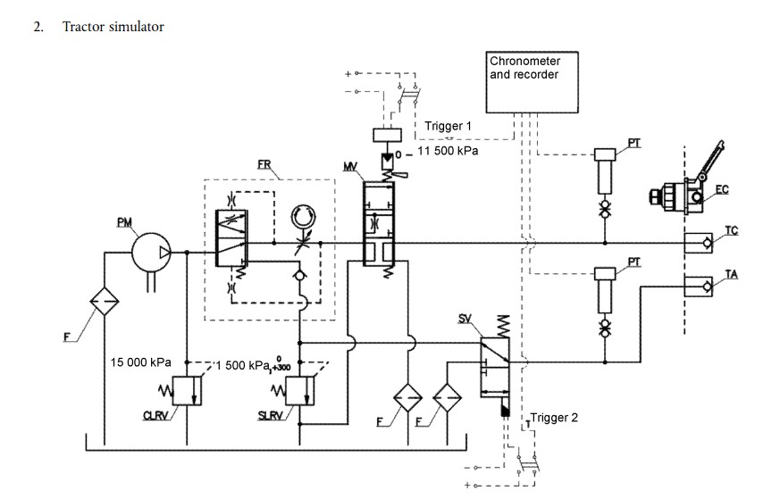
F = filters
PM = pump
PT = pressure transducers
CLRV = control line relief valve
SLRV = supplementary line relief valve
L 17/58 EN Official Journal of the European Union 23.1.2015
SV = 3 way solenoid valve
FR = flow regulator
MV = proportional modulation valve
TA = coupling head, supplementary line (male coupling ISO 16028:2006)
TC = coupling head, control line (male coupling ISO 5676:1983)
EC = electrical connection (female ISO 7638:2003)
Scope of delivery:
- The test bench is delivered with a calibration certificate issued by a metrology service accredited according to SO/IEC 17025:2017, containing measurement uncertainty and reference information and valid for one year from the date of commissioning.

