Kategoriler
Tractor Testing RAAGEN IPX1 IPX2 IPX3 IPX4 WATER SPRAY TEST CHAMBER Automotive RAAGEN RAIN TEST CHAMBER MIL-STD-810 Building Materials Test Cement, Concrete, Bricks, Asphalt and Rock Test Ceramics Glass Test Components Test Composites Test Container & Package Testing Clımatıcs & Envıronmental Sımulatıon MIL STD 810 Testing Structural Dynamıcs Testıng
Measuring Device for Testing Vehicles Equipped with Pneumatic Brakes for the Time of Operation of the Brake Drive According to the Methods of UNECE Rule 13 (Model: R-BTM-13 Vehicle Control System)
Model: R-BTM-13
The principle of operation of the device is based on receiving signals and data from pressure sensors included in the device, measuring time intervals using an electronic chronometer built into the CTU unit, exchanging digital information in the electrical connection between the towing and towed vehicle. Data processing occurs using the software supplied with the device.
Pneumatic control lines simulator following features
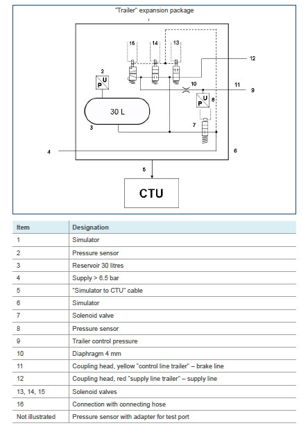
- It has a reservoir with a capacity of 30 liters which is charged to a pressure of 650 kPa before each test and which is not recharged during each test. At the outlet of the braking control device, the simulator incorporates an orifice with a diameter of from 4.0 to 4.3 mm inclusive. The volume of the pipe measured from the orifice up to and including the coupling head is 385 ± 5 cm3 (which is deemed to be equivalent to the volume of a pipe 2.5 m long with an internal diameter of 13 mm and under a pressure of 650 kPa). The control line pressures referred to in paragraph 3. of this annex is measured immediately downstream of the orifice.
- The braking system control is so designed that its performance in use is not affected by the tester.
- The simulator is set, e.g. through the choice of orifice in accordance with paragraph 1.1 of this annex in such a way that, if a reservoir of 385 cm3±5 cm3 is joined to it, the time taken for the pressure to increase from 65 to 490 kPa (10 and 75 percent respectively of the nominal pressure of 650 kPa) is 0.2 second ±0.01 second. If a reservoir of 1,155 cm3 ±15 cm3 is substituted for the above-mentioned reservoir, the time taken for the pressure to increase from 65 to 490 kPa without further adjustment will be 0.38 second ±0.02 second. Between these two pressure values, the pressure increase in an approximately linear way.
These reservoirs are connected to the coupling head without using flexible pipes. The connection between the reservoirs and the coupling head has an internal diameter of not less than 10 mm.
The setting is carried out using a coupling head arrangement that is representative of the type fitted to the trailer for which type approval is sought.
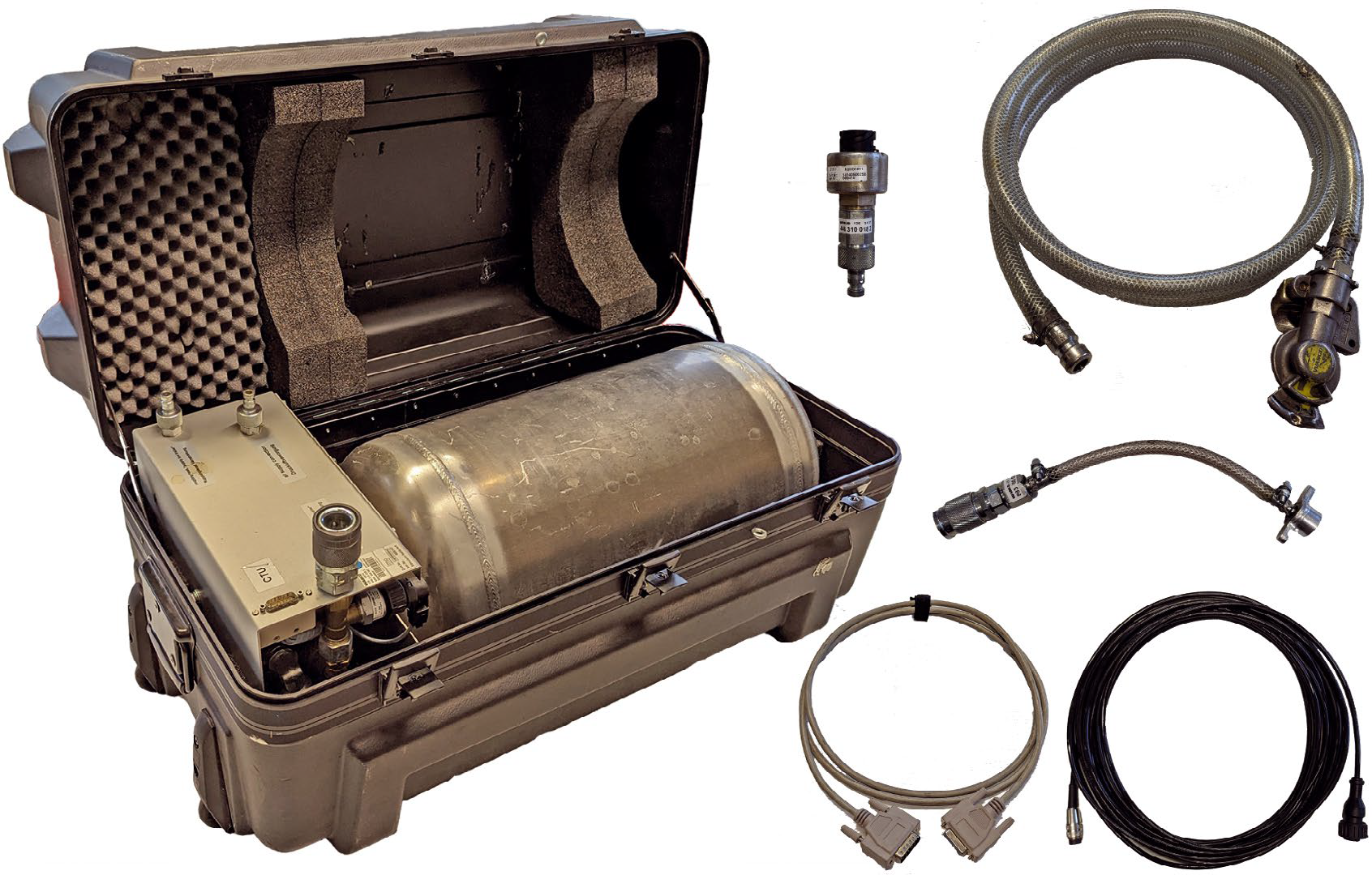
Scope of delivery:
- The test bench is delivered with a calibration certificate issued by a metrology service accredited according to SO/IEC 17025:2017, containing measurement uncertainty and reference information and valid for one year from the date of commissioning.
- Rugged laptop with software, includes all cables, pressure sensors, hoses with adapters
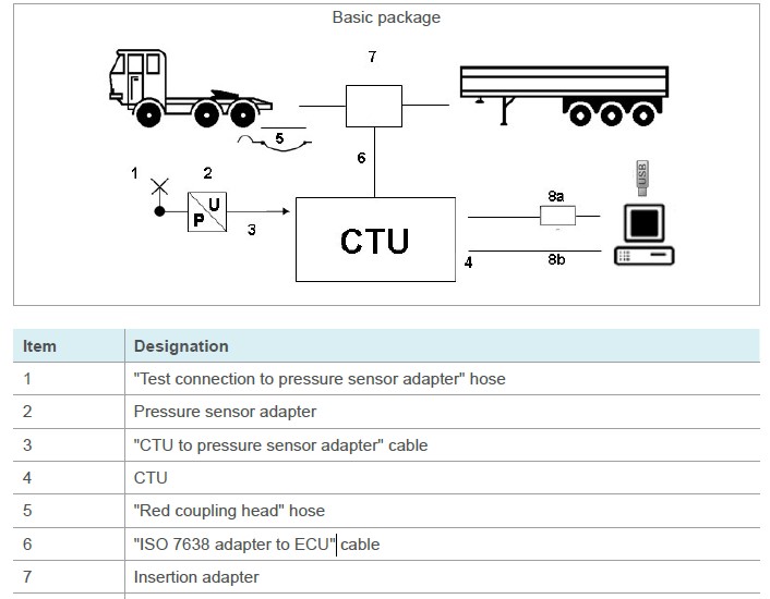
- CTU Basic package
The basic package can be used to carry out tests on the ISO 7638 port.
The basic package enables the electronic verification of the towing vehicle/trailer ISO 7638 port (EBS socket) as well as a towing vehicle/trailer simulation. The basic package is accommodated in an accessories case and includes the basic electronic equipment for the performance and evaluation of investigations. The basic package also includes components which are required in both the towing vehicle and the trailer (pressure sensor for the least favourably positioned wheel brake cylinder including a pressure sensor cable as well as connector element for the wheel brake cylinder and hose to the red coupling head).
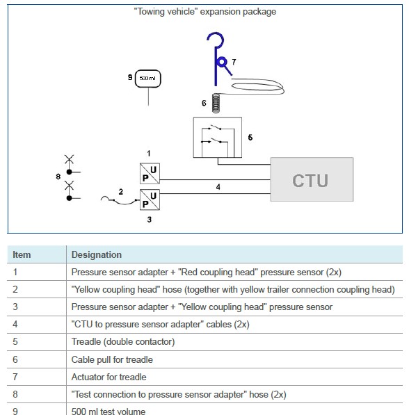
- Towing vehicle expansion package
Together with the basic package, this expansion package is particularly suitable for towing vehicle manufacturers who use the CTU for system verifications and optimisation, for example.
The "Towing vehicle" expansion package comprises components for performing pressure flow time records and measurements on the towing vehicle.
The components of the "Towing vehicle" expansion package are included in the accessories case if ordered.
The "Towing vehicle" expansion package consists of the following components:
- Trailer expansion package
Together with the basic package, the "Trailer" expansion package is particularly suitable for trailer manufacturers who also use the CTU for system verifications and optimisation, for example.
The "Trailer" extension package includes:
- simulator for simulating the towing vehicle behaviour (in accordance with UNECE R13 annex to Annex 6)
- ensuring the pneumatic supply of the trailer vehicle
- generating sudden brake applications
- various cables
- components for trailer verification in accordance with UNECE R13
- provision of the compressed air supply to the reservoir from an in-house unit (or from a towing vehicle)
The measurement recorder components required for connecting to the wheel brake cylinder are provided in the basic package. The components of the "Trailer" expansion package are accommodated in the accessories case in which the simulator is located.
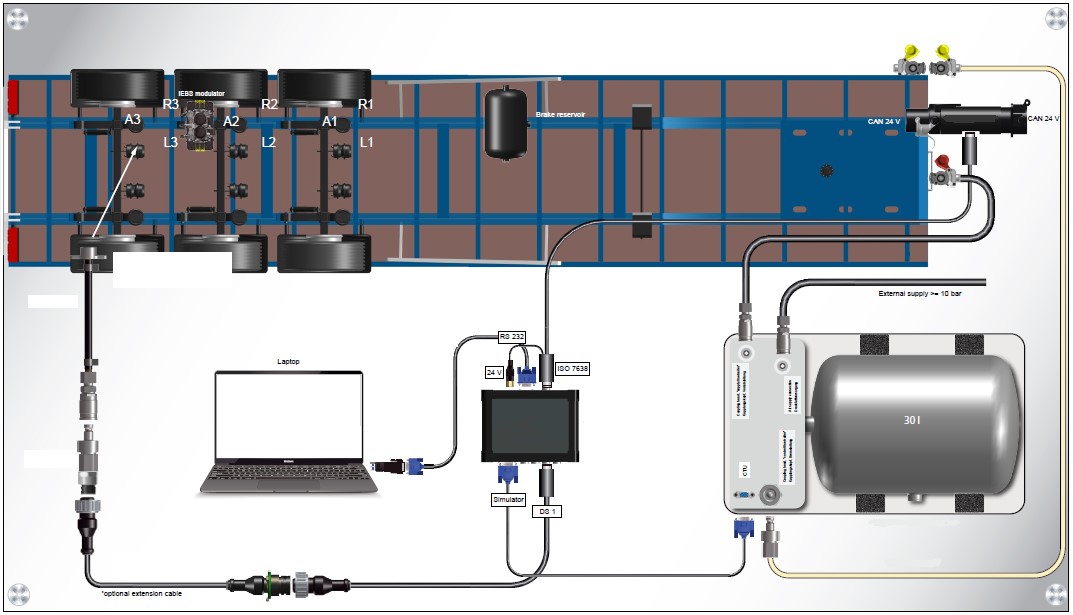
The diagrams give an example of the correct configuration of the simulator for setting and use:
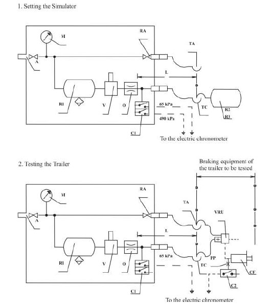
A = Supply connection with shut-off valve
C1 = Pressure switch in the simulator, set at 65 kPa and at 490 kPa
C2 = Pressure switch to be connected to the brake actuator of the trailer, to operate at
75 per cent of the asymptotic pressure in the brake actuator CF
CF = Brake cylinder
L = Line from orifice O up to and including its coupling head TC, having an inner
volume of 385 ± 5 cm3 under a pressure of 650 kPa
M = Pressure gauge
O = Orifice with a diameter of not less than 4 mm and not more than 4.3 mm
PP = Pressure test connection
R1 = 30 litre air reservoir with drain valve
R2 = Calibrating reservoir, including its coupling head TC, to be 385 ± 5 cm3
R3 = Calibrating reservoir, including its coupling head TC, to be 1155 ± 15 cm3
RA = Shut-off valve
TA = Coupling head, supply line
V = Braking system control device
TC = Coupling head, control line
VRU = Emergency relay valve
The simulator for checking the response to signals transmitted via the electric control line has the following characteristics:
- The simulator produces a digital demand signal in the electric control line according to ISO 11992- 2:2003 and its Amd.1:2007 and provides the appropriate information to the trailer via pins 6 and 7 of the ISO 7638:2003 connector. For the purpose of response time measurement the simulator may at the manufacturer’s request transmit to the trailer information that no pneumatic control line is present and that the electric control line demand signal is generated from two independent circuits (see paragraphs 6.4.2.2.24. and 6.4.2.2.25. of ISO 11992-2:2003 and its Amd.1:2007).
- The braking system control is designed that its performance in use is not affected by the tester.
- For the purpose of response time measurement the signal produced by the electric simulator is equivalent to a linear pneumatic pressure increase from 0.0 to 650 kPa in 0.2 ± 0.01 second.
- The diagrams give an example of the correct configuration of the simulator for setting and use.
The provided information is for general description purposes only. Please refer to the official UNECE R13 regulations for detailed testing procedures and specifications.

